ESP32 Controlled Thermostat
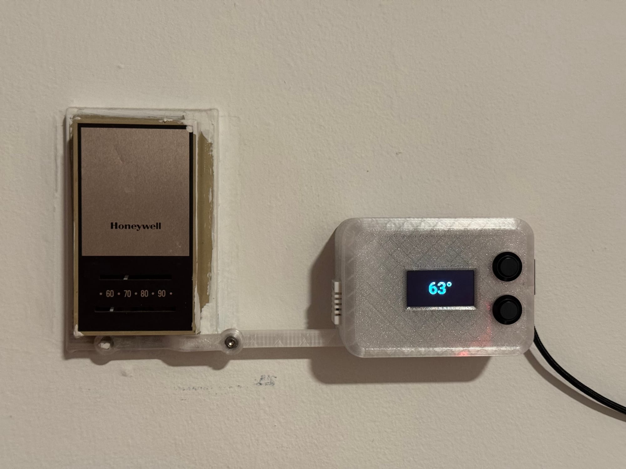
Late Last year as the weather began to cool off, I decided I needed a better way to automate control of the heat within our New York City apartment. I wanted to do this in a renter friendly way but the challenge was that we have a very old Honeywell thermostat on the wall. Enter the idea for a device that would push and pull the lever on the thermostat using a servo controlled by ESPHome.
BOM
1 - ESP32-S3
2 - Momentary Buttons
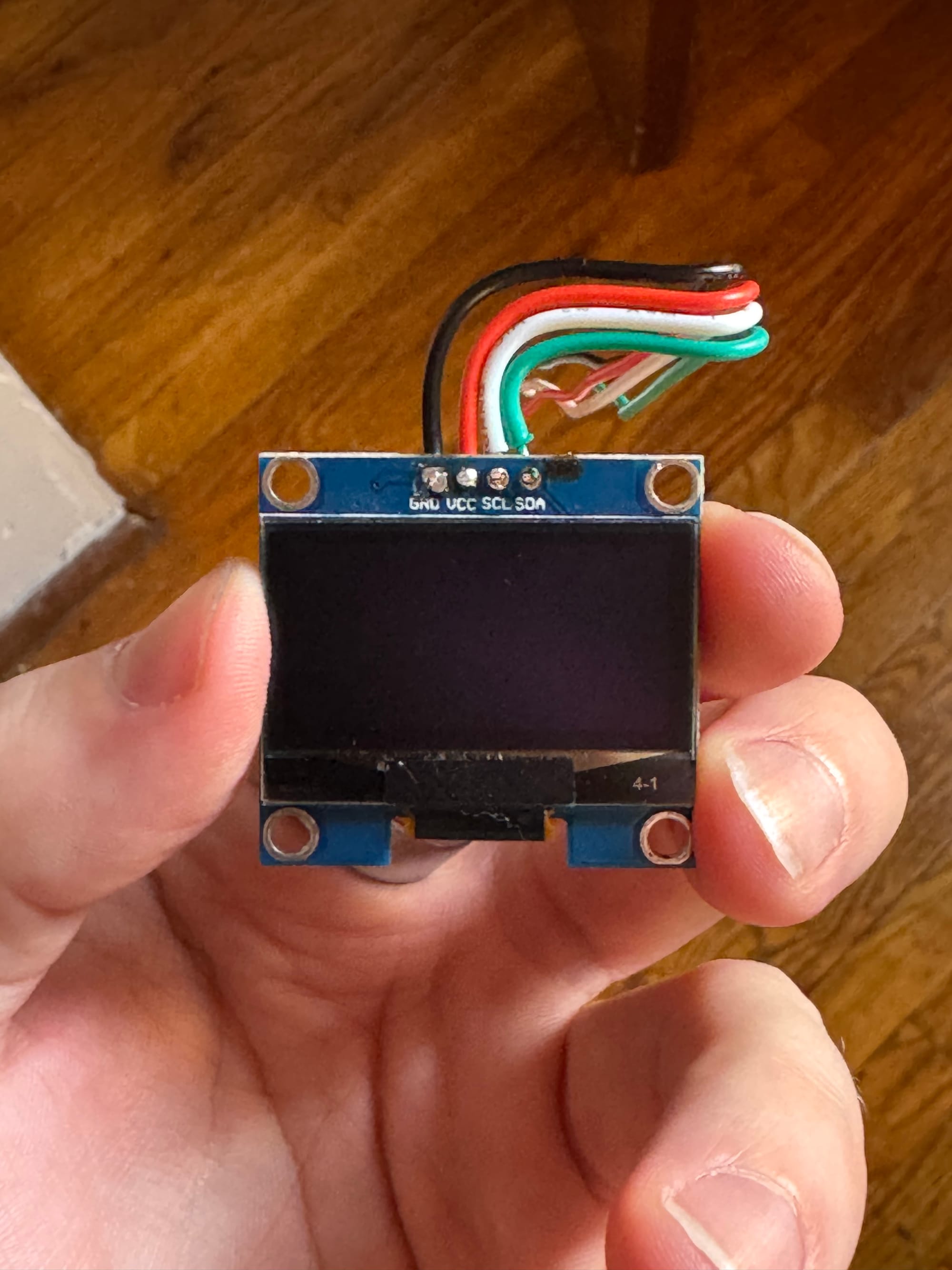
1 - SSD1106 1.3" OLED Screen
1 - DHT22 Temperature / Humidity Sensor
1 - Tiny Roller Bearing
5 - M3 x 8mm SHCS
3 - M4 x 12mm SHCS
1 - Assortment of 24AWG wire
1 - 3 Part 3D Printed Case
Design Overview
The primary goal of this project was to design a smart device that could live permanently on the wall in our entry way to control the the legacy thermostat. This meant that I wanted the design to be fully contained and aesthetically attractive.
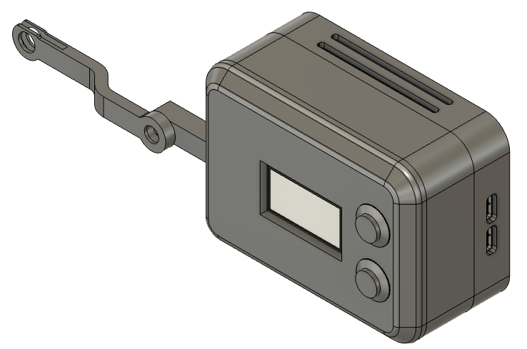
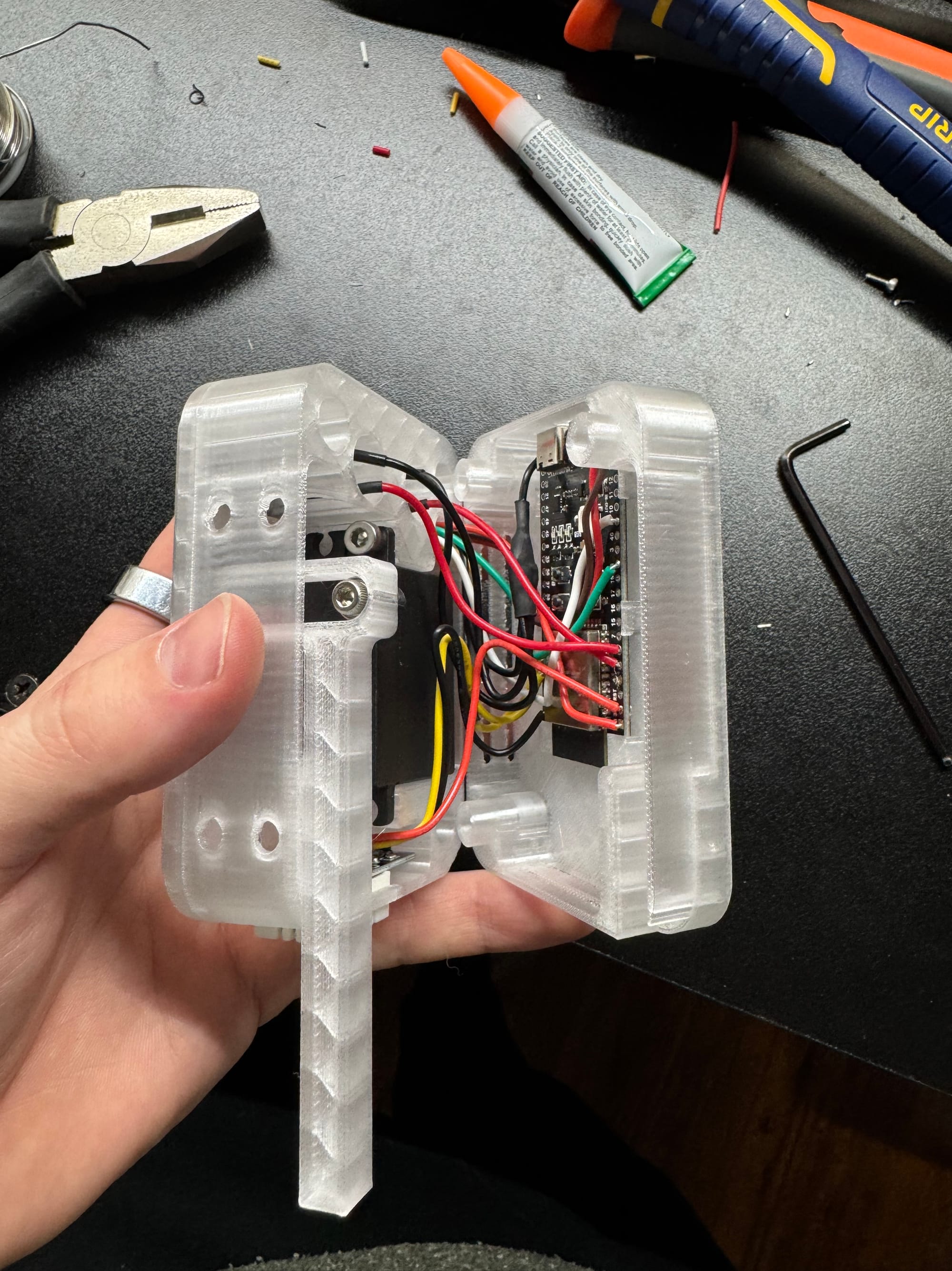
To achieve the functionality while making the assembly easy I went with a 3 layer stack. The top layer holds the SSD1106 OLED screen, the middle layer houses the servo, the DHT22, and the momentary buttons, and the back layer holds the ESP32-S3. The stack is then secured together with a few socket head cap screws from the back side to provide clean aesthetic from the front.
Assembly
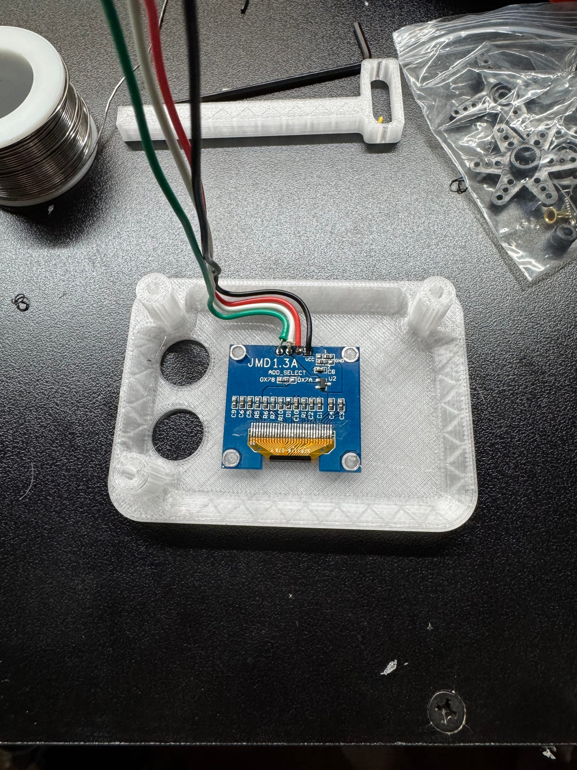
I started by soldering leads to the screen then installing the screen to the front section of the case. The case has small pins to align the screen to the opening then the screen is secured with a few drops of CA glue.
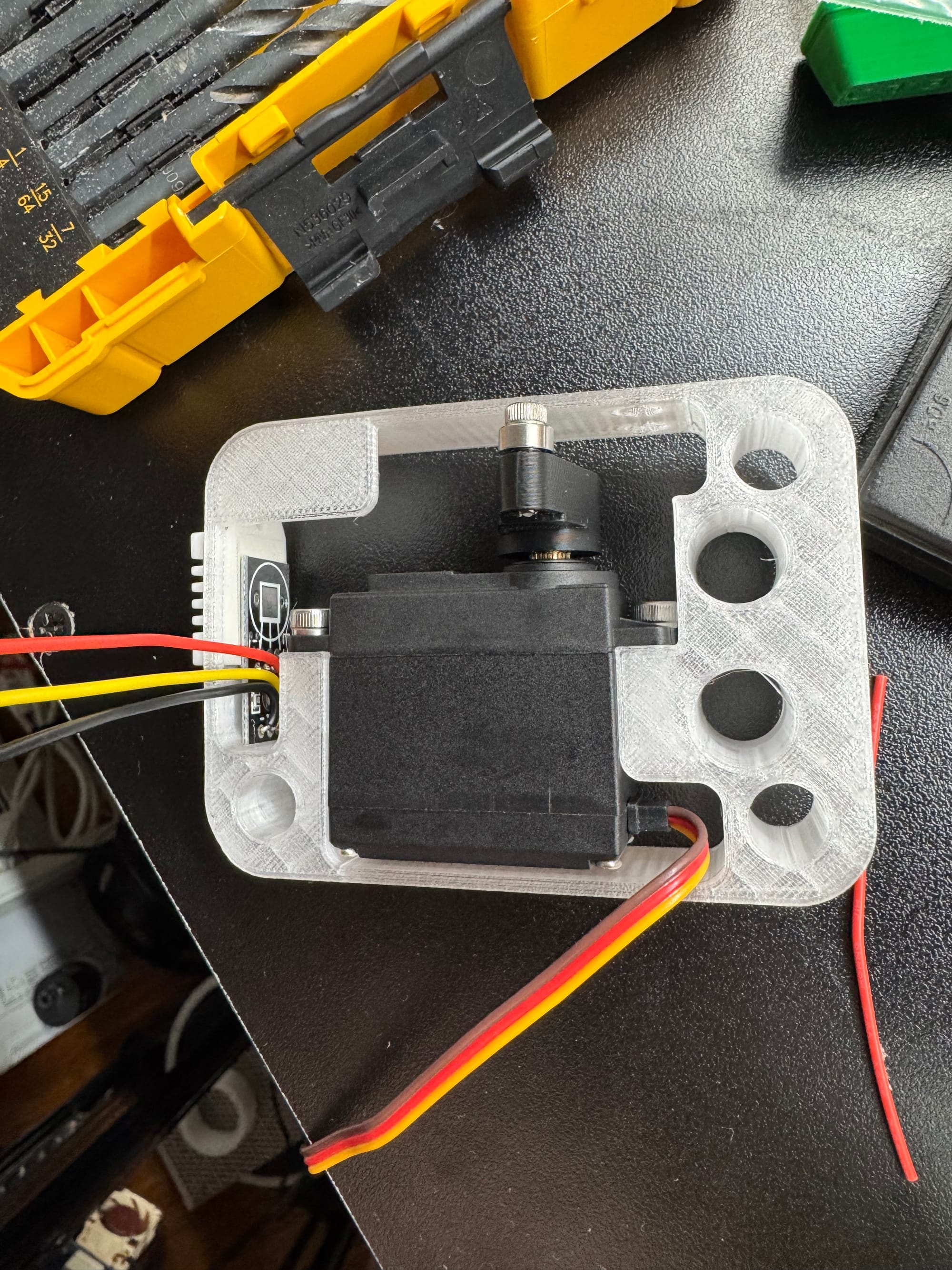
Next, the servo arm is connected to the servo then that assembly is mounted to the middle section of the case. The DHT22 also goes is press fit into the cutout on the side of the case at this time.
Next, I installed the momentary buttons. Then connected the front section of the case to the middle and routed the wires for the SSD1106 through
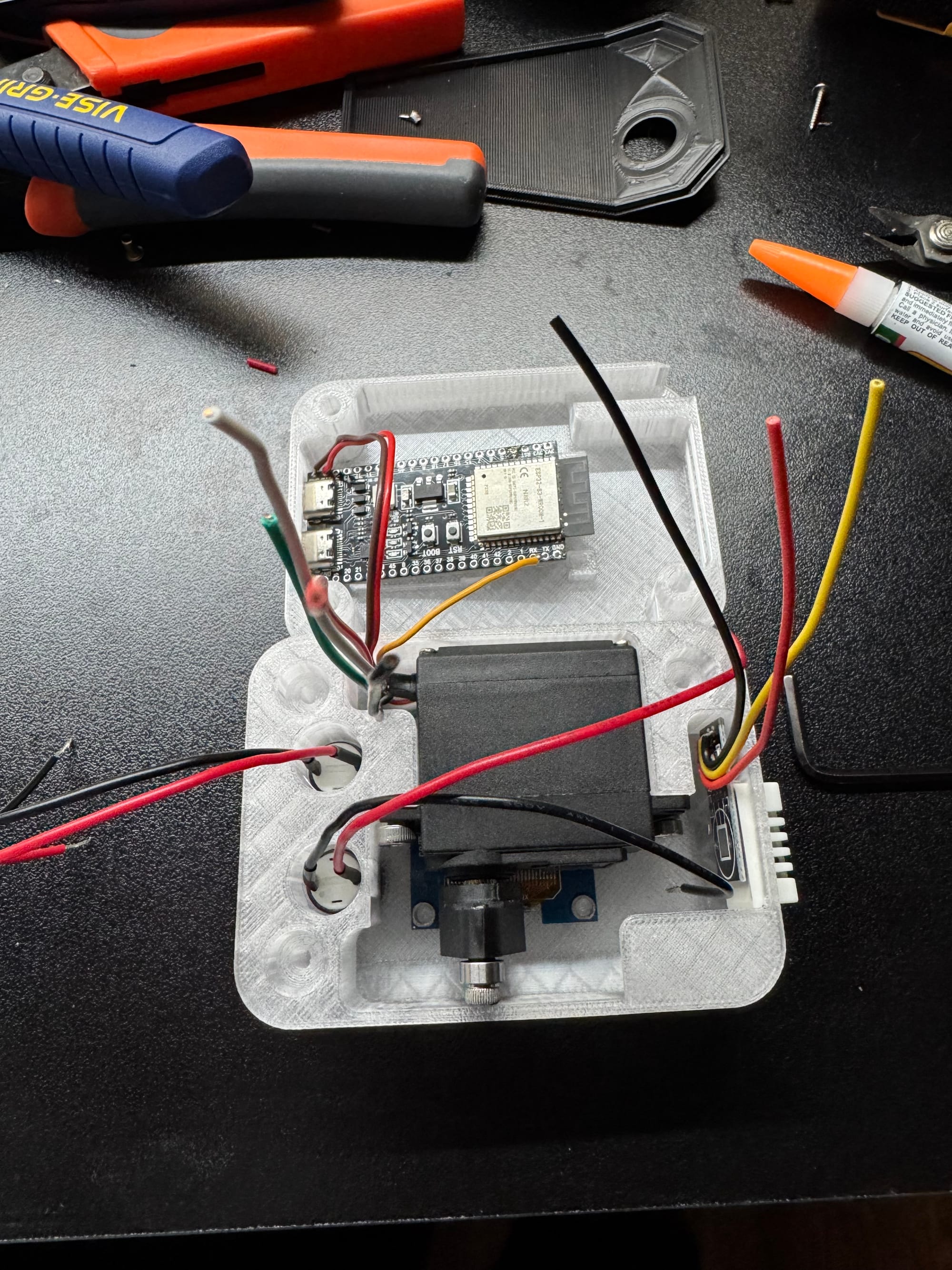
At this point I was realizing that there were going to be a lot more wires in a smaller space than I had originally pictured. However, with some creative folds and routing I was able to make it fit.
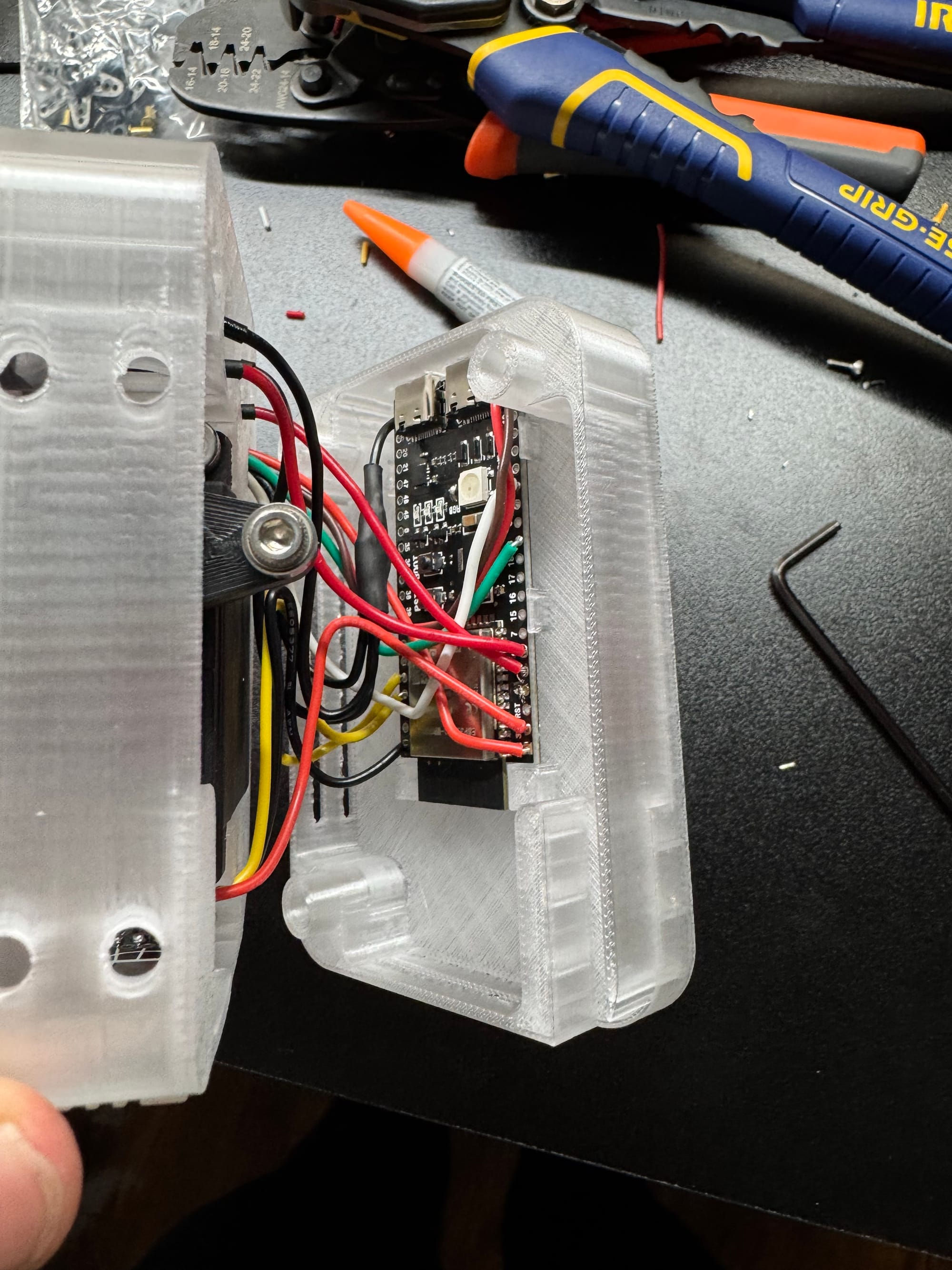
Finally, I installed a stand-in push rod and was ready to configure the software and start testing.
Wiring
Screen:
GND
VCC - 3.3V
SCL - GPIO09 - White
SDA - GPIO08 - Green
Servo:
GND
VCC - 5V
PWM - GPIO02
Temp Sensor:
GND
VCC - 3.3V-6V
Signal - GPIO01
Button 1:
GND
Signal - GPIO16
Button 2
GND
Signal - GPIO17
Software
As a long time Home Assistant user many of my projects run on ESPHome due to the fantastic integration and shear flexibility of the system.
Flashing the ESP32 with ESPHome as become so easy with their web based flashing tool.
After a few iterations of figuring out what information I wanted on the screen and how to lay it out I ended up with the ESPHome YAML configuration below.
esphome:
name: thermostat-actuator
friendly_name: thermostat-actuator
esp32:
board: esp32-s3-devkitc-1
framework:
type: arduino
# Enable logging
logger:
# Enable Home Assistant API
api:
encryption:
key: "KEY"
services:
- service: control_servo
variables:
level: float
then:
- servo.write:
id: servo0
level: !lambda 'return level / 100.0;'
ota:
- platform: esphome
password: "PASSWORD"
wifi:
ssid: !secret wifi_ssid
password: !secret wifi_password
# Enable fallback hotspot (captive portal) in case wifi connection fails
ap:
ssid: "Thermostat-Actuator"
password: "PASSWORD"
captive_portal:
binary_sensor:
- platform: gpio
name: 'Button Up'
pin:
number: GPIO18
mode: INPUT_PULLUP
filters:
- invert:
- platform: gpio
name: 'Button Down'
pin:
number: GPIO17
mode: INPUT_PULLUP
filters:
- invert:
i2c:
sda: GPIO9
scl: GPIO08
display:
- platform: ssd1306_i2c
model: 'SH1106 128x64'
rotation: 0
lambda: |-
if (id(screen).state) {
it.printf(64, 32, id(roboto_32), TextAlign::CENTER, "%.0f°", id(average_temp).state);
it.printf(64,56, id(roboto_12), TextAlign::CENTER, "Set: %.0f°", id(radiator_set_point).state);
}
else {
it.fill(COLOR_OFF);
}
font:
- file:
type: gfonts
family: Roboto
weight: 500
id: roboto_32
size: 32
- file:
type: gfonts
family: Roboto
weight: 100
id: roboto_12
size: 12
sensor:
- platform: dht
pin: GPIO01
temperature:
name: 'Entry Temperature'
id: entry_temp
humidity:
name: 'Entry Humidity'
id: entry_hum
update_interval: 60s
- platform: homeassistant
entity_id: input_boolean.thermostat_screen
id: screen
- platform: homeassistant
entity_id: input_number.radiator_temperature
id: radiator_set_point
- platform: homeassistant
entity_id: sensor.average_house_temperature
id: average_temp
servo:
- id: servo0
output: pwm_output
auto_detach_time: 5s
min_level: 3%
max_level: 12.0%
# On ESP32, use ledc output
output:
- platform: ledc
id: pwm_output
pin: GPIO02
frequency: 50 Hz
number:
- platform: template
id: servoControl
name: Servo Control
min_value: -90
initial_value: 0
max_value: 90
step: .5
optimistic: true
set_action:
then:
- servo.write:
id: servo0
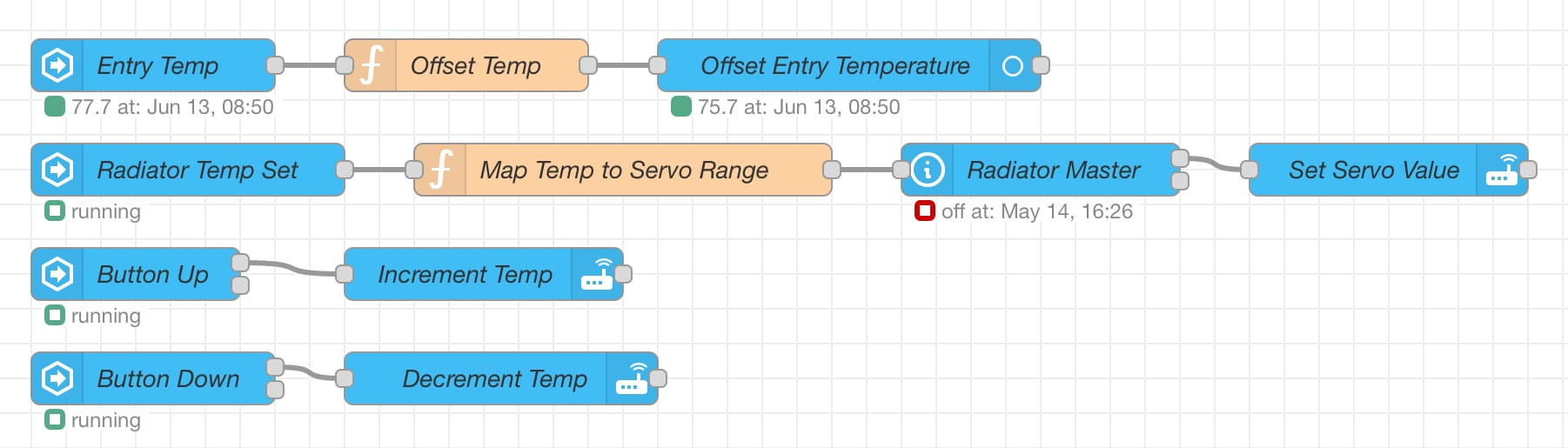
level: !lambda 'return x / 100.0;'The other half of the software puzzle for this device was Node Red. Below is an overview of the flows used on the Home Assistant server.
Testing
To my shock this was one of those projects that just kind of worked on the first try. After flashing the device with ESPHome and adding it to my Home Assistant server I was able to see the buttons and sensors and I was able to control the servo.
One thing I thought was going to be difficult to overcome was that the thermostat has a pivot arm that is about 75mm and the servo is using a Scotch Yoke which has an output of a sine wave. So I thought it was going to be difficult to find an equation that would accurately output servo positions based on desired temperatures.
After gathering a handful of data points and spending more time than I would like to admit in excel trying to find a multiple order polynomial that would fit the points; I was able to just use a simple linear equation. This was then used to create the code the for the Map Temp to Servo Range node seen the Node Red screenshot above. That code can be seen below.
var temp = msg.payload;

var mapped_value = 0.0;
var offset = 2;

mapped_value = Math.round(5.9*(temp-offset)-412);

msg.payload = mapped_value;

return msg;
This takes the temperature in from an input_number helper, applies an offset, and maps that to a servo position based on the equation found earlier.
Functionality
I believe that most smart devices should still retain some manner of physical control. Finding your phone to open an app to change the temperature is just too much overhead for a device that may be used daily. Therefore, interaction with the device was left to be very simple. The top button increments the thermostat set point by 1°F and the lower button decrements it by the same amount. This allowed for quick and easy changes to the set point while allowing Home Assistant to automate the function the majority of the time.
On screen I wanted things to be simple as well. In large font at the center we have the average temperature of all the sensors in the apartment. In small text below that the current set point is shown. This allows the current temperature to be read from across the room while the set point can be read when you are in front of the device to make a change.
Conclusion, Learnings, and Findings
All in all, both my partner and I are very happy with how this project turned out. After creating automations to adjust the temperature based on time of day, outside temperature, and proximity to home it was a very comfortable even during a very cold NYC winter. I was able to preheat the apartment in the afternoons while we were at work but if we went on vacation the heat would stay off to save us money.
One of my biggest takeaways from this project was that wires take up much more space than I thought they would. I had left about a 6-8mm gap in the stack to accommodate the wires but after soldering everything together it was still a tight fit to the the case to close.
Another learning moment was to not over complicate things unless you need to. I jumped straight to a multiple order polynomial for the positioning without even trying a linear fit. This created a lot of headaches and confusion that weren't needed. If I had started with the basic solution first I could always expand to more complex solutions after gaining a base understanding.
Thanks for reading and stay tuned for future projects.